Review Notes on Light Waves
A light wave is an electromagnetic wave which travels through the vacuum of outer space. Light waves are produced by vibrating electric charges., An electromagnetic wave is a transverse wave which has both an electric and a magnetic component.
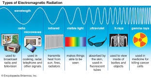
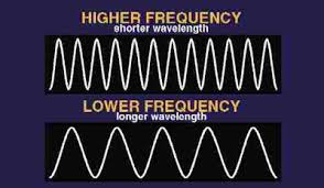
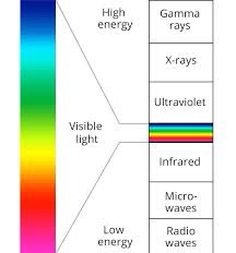
Electromagnetic waves exist with an enormous range of frequencies. This continuous range of frequencies is known as the electromagnetic spectrum. The entire range of the spectrum is often broken into specific regions. The subdividing of the entire spectrum into smaller spectra is done mostly on the basis of how each region of electromagnetic waves interacts with matter. The longer wavelength, lower frequency regions are located on the far left of the spectrum and the shorter wavelength, higher frequency regions are on the far right.
Visible light region – the very narrow band of wavelengths located to the right of the infrared region and to the left of the ultraviolet region. Each individual wavelength within the spectrum of visible light is a representative of a particular color. That is, when light of that particular wavelength strikes the retina of our eye, we perceive that specific color sensation.
Isaac Newton showed that light shining through a prism will be separated into its different wavelengths and will thus show the various colors that visible light is comprised of. The separation of visible light into its different colors is known as dispersion. Each color is characteristic of a distinct wavelength; and different wavelengths of light waves will bend varying amounts upon passage through a prism; for these reasons, visible light is dispersed upon passage through a prism.. The red wavelengths of light are the longer wavelengths and the violet wavelengths of light are the shorter wavelengths. Between red and violet, there is a continuous range or spectrum of wavelengths. The visible light spectrum is shown in the diagram below.
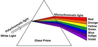
When all the wavelengths of the visible light spectrum strike your eye at the same time, white is perceived. Thus, visible light is sometimes referred to as white light. Technically speaking, white is not a color at all, but rather the combination of all the colors of the visible light spectrum. If all the wavelengths of the visible light spectrum give the appearance of white, then none of the wavelengths would lead to the appearance of black. Once more, black is not actually a color. Technically speaking, black is merely the absence of the wavelengths of the visible light spectrum. So when you are in a room with no lights and everything around you appears black, it means that there are no wavelengths of visible light striking your eye as you sight at the surroundings.
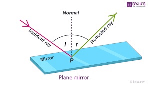
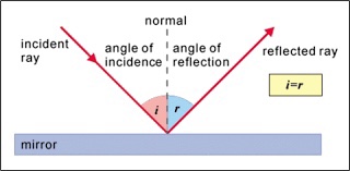
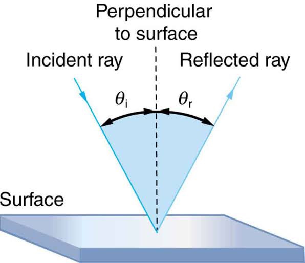
Law of reflection. The diagram below illustrates the law of reflection.
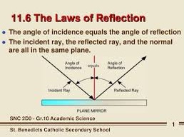
In the diagram, the ray of light approaching the mirror is known as the incident ray(labeled I in the diagram). The ray of light which leaves the mirror is known as the reflected ray (labeled R in the diagram). At the point of incidence where the ray strikes the mirror, a line can be drawn perpendicular to the surface of the mirror; this line is known as a normal line (labeled N in the diagram). The normal line divides the angle between the incident ray and the reflected ray into two equal angles. The angle between the incident ray and the normal is known as the angle of incidence. The angle between the reflected ray and the normal is known as the angle of reflection. (These two angles are labeled with the Greek letter “theta” accompanied by a subscript; read as “theta-i” for angle of incidence and “theta-r” for angle of reflection.) The law of reflection states that when a ray of light reflects off a surface, the angle of incidence is equal to the angle of reflection.
The diagram below depicts two beams of light incident upon a rough and a smooth surface.
Smooth surfaces produce images through a process called normal reflecton.
Rough surfaces do not produce an image, this is called diffuse relfection.
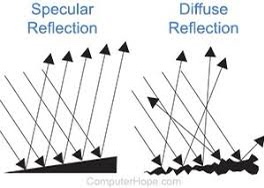
Both types of reflection follow the law of reflection (angle in incidence equals the angle of reflection) In diffuse reflection the light rays come down parallel but hit the surface at different angles so they reflect at different angles producing a scattering effect.
Plane Mirror
In the case of plane mirrors, the image is said to be a virtual image. Virtual images are images which are formed in locations where light does not actually reach. Light does not actually pass through the location on the other side of the mirror; it only appears to an observer as though the light were coming from this position. Whenever a mirror (whether a plane mirror or otherwise) creates an image which is virtual, it will be located behind the mirror where light does not really pass
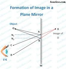
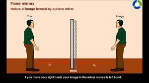
The diagram depicts some important information about plane mirrors: Images formed by plane mirrors are virtual, upright, left-right reversed, the same distance from the mirror as the object’s distance, and the same size as the object.
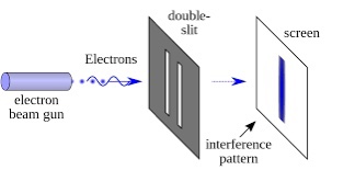
Double Slit Experiment (diffraction, interference an standing waves)
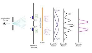
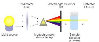
In 1801, Thomas Young successfully showed that light does produce an interference pattern. In order to produce such a pattern, monochromatic light must be used. Monochromatic light is light of a single color; by use of such light, the two sources will vibrate with the same frequency. It is also important that the two light waves be vibrating in phase with each other; that is, the crest of one wave must be produced at the same precise time as the crest of the second wave. (This is often referred to as coherent light.) To accomplish this, Thomas Young used a single light bulb and projected the light bulb onto two pinholes. The light from the bulb will then diffract through the pinholes and the pattern can be projected onto a screen. Since there is only one source of light, the set of two waves which emanate from the pinholes will be in phase with each other. As expected, the use of a monochromatic light source and pinholes to generate in-phase light waves resulted in a pattern of alternating bright and dark bands on the screen. A typical appearance of the pattern is shown below.
Polerization
A light wave which is vibrating in more than one plane is referred to as unpolarized light. Light emitted by the sun, by a lamp in the classroom, or by a candle flame is unpolarized light. Such light waves are created by electric charge which vibrates in a variety of directions, thus creating an electromagnetic wave which vibrates in a variety of directions.
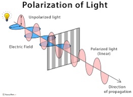
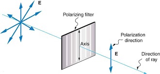
It is possible to transform unpolarized light into polarized light. Polarized light waves are light waves in which the vibrations occur in a single plane. The process of transforming unpolarized light into polarized light is known as polarization.
The most common method of polarization involves the use of a Polaroid filter. Polaroid filters are made of a special material which is capable of blocking one of the two planes of vibration of an electromagnetic wave. (Remember, the notion of two planes or directions of vibration is merely a simplification which helps us to visualize the wavelike nature of the electromagnetic wave.). When unpolarized light is transmitted through a Polaroid filter, it emerges with one-half the intensity and with vibrations in a single plane; it emerges as polarized light.
Refraction
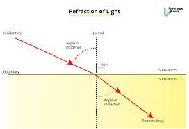
Since refraction of light occurs when it crosses the boundary, visual distortions often occur. These distortions occur when light changes medium as it travels from the object to our eyes.
Refraction is the bending of the path of a light wave as it passes from one material to another material. The refraction occurs at the boundary and is caused by a change in the speed of the light wave upon crossing the boundary. The tendency of a ray of light to bend one direction or another is dependent upon whether the light wave speeds up or slows down upon crossing the boundary.
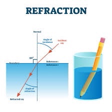
The transmission of light across a boundary between two medium is accompanied by a change in both the speed and wavelength of the wave. The light wave not only changes directions at the boundary, it also speeds up or slows down and transforms into a wave with a larger or a shorter wavelength. The only time that a wave can be transmitted across a boundary, change its speed, and still not refract is when the light wave approaches the boundary in a direction which is perpendicular to it. As long as the light wave changes speed and approaches the boundary at an angle, refraction is observed.
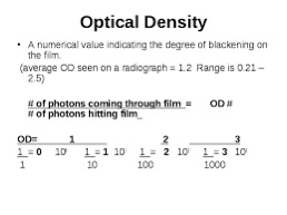
In the case of an electromagnetic wave, the speed of the wave depends upon the optical density of that material. The optical density of a medium is not the same as its physical density. The physical density of a material refers to the mass/volume ratio. The optical density of a material relates to the sluggish tendency of the atoms of a material to maintain the absorbed energy of an electromagnetic wave in the form of vibrating electrons before reemitting it as a new electromagnetic disturbance. The more optically dense which a material is, the slower that a wave will move through the material.
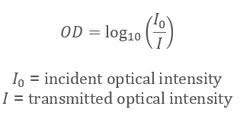
ne indicator of the optical density of a material is the index of refraction value of the material. Index of refraction values (represented by the symbol n) are numerical index values which are expressed relative to the speed of light in a vacuum. The index of refraction value of a material is a number which indicates the number of times slower that a light wave would be in that material than it is in a vacuum. A vacuum is given an n value of 1.0000. The n values of other materials are found from the following equation:
Light Traveling from a Fast to a Slow Medium
If a ray of light passes across the boundary from a material in which it travels fast into a material in which travels slower, then the light ray will bend towards the normal line.
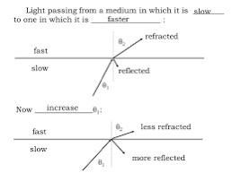
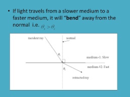
Light Traveling from a Slow to a Fast Medium
If a ray of light passes across the boundary from a material in which it travels slow into a material in which travels faster, then the light ray will bend away from the normal line.
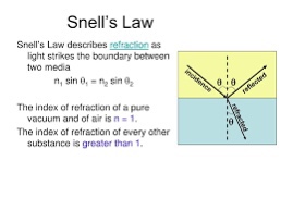
The equation is known as the Snell’s Law
where (“theta i”) = angle of incidence
(“theta r”) = angle of refraction
ni = index of refraction of the incident medium
nr = index of refraction of the refractive medium
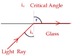
The Critical Angle
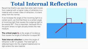
The critical angle; it is the largest angle of incidence for which refraction can still occur. For any angle of incidence greater than the critical angle, light will undergo total internal reflection.
Total Internal Reflection
Total internal reflection, or TIR as it is intimately called, is the reflection of the total amount of incident light at the boundary between two medium.
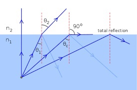
Total internal reflection (TIR) is the phenomenon which involves the reflection of all the incident light off the boundary. TIR only takes place when both of the following two conditions are met:
- the light is in the more dense medium and approaching the less dense medium.
- the angle of incidence is greater than the so-called critical angle.
LENS

Guidelines for rays falling on the concave and convex lenses
- When a ray strikes concave or convex lenses obliquely at its pole, it continues to follow its path.
- When a ray, parallel to the principal axis strikes concave or convex lenses, the reflected ray passes through a focus on the principal axis.
- When a ray, passing through focus strikes concave or convex lenses, the reflected ray will pass parallel to the principal axis.
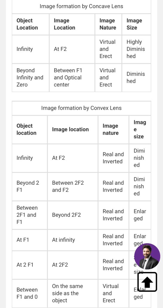
Image Formation by Concave and Convex Lenses:
Convex Lenses
- When an object is placed at infinity, the real image is formed at the focus. The size of the image is much smaller than that of the object.

- When an object is placed behind the center of curvature, the real image is formed between the center of curvature and focus. The size of the image is the same as compared to that of the object.

- When an object is at the center of curvature, the real image is formed at the other center of curvature. The size of the image is the same as compared to that of the object.

- When an object is placed in between the center of curvature and focus, the real image is formed behind the center of curvature. The size of the image is larger than that of the object.

- When an object is placed at the focus, a real image is formed at infinity. The size of the image is much larger than that of the object.

- When an object is placed in between focus and pole, a virtual image is formed. The size of the image is larger than that of the object.

Concave Lenses
- When an object is placed at infinity, a virtual image is formed at the focus. The size of the image is much smaller than that of the object.

- When an object is placed at a finite distance from the lens, a virtual image is formed between the pole and the focus of the convex lens. The size of the image is larger than that of the object.

Summary of Image Formation by Concave and Convex Lens
Frequently Asked Questions – FAQs
Which type of lens is known as a converging lens?
Convex lenses are also known as converging lenses.
Why concave lenses are known as diverging lenses?
Concave lenses are known as diverging lenses since they diverge rays after falling on the concave lens.
Which lens have negative focal length?
Concave has negative focal length.
Which lens is thicker in the middle and thinner at the edges?
Convex lens is thicker in the middle and thinner at the edges.
Where are concave lenses used?
Concave lenses are used in telescopes, and spy holes in the doors.
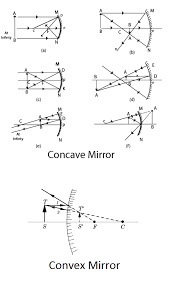
IMAGES FORMED BY A CONVEX MIRROR
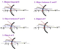
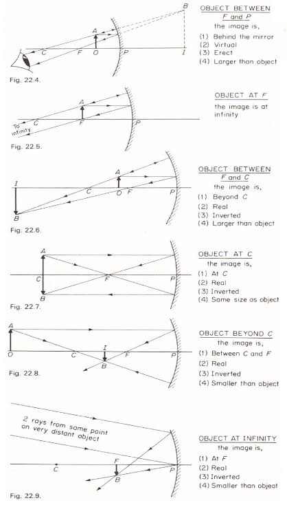
IMAGES FORMED BY CONCAVE MIRRORS


Leave a comment